
English
Every object above absolute zero emits infrared radiation. Capturing this invisible energy and translating it into accurate, actionable data requires highly specialized optoelectronics. Specifying the wrong thermal technology—whether misunderstanding spectral bands, sensor cooling requirements, or lens materials—results in failed inspections, compromised perimeter security, and wasted capital expenditure. To evaluate and select the right equipment, technical buyers must understand the exact mechanical and computational processes a camera uses to convert raw infrared energy into a precise thermogram.
We will break down the physics, the internal hardware architecture, and the software algorithms that make thermal detection possible. This knowledge separates effective field deployments from expensive miscalculations. When you mount a sensor on a 50-foot pole at a substation or along a harsh coastal border, you need to know exactly how it processes heat signatures. Understanding the signal path from the lens to the final digital output ensures you specify a device capable of surviving and performing in your specific environment.
Thermal cameras do not "see" temperature; they detect infrared radiation intensity and temperature differences (Delta T), using complex algorithms to calculate and display estimated surface temperatures.
The conversion process relies on specialized lenses (like Germanium) and Focal Plane Arrays (FPAs) that change electrical resistance when exposed to infrared energy.
Selecting between cooled and uncooled sensors dictates the camera's thermal sensitivity (NETD), maintenance lifecycle, and suitability for long-range detection.
Accuracy in real-world applications requires accounting for environmental variables, specifically object emissivity, atmospheric attenuation, reflected apparent temperature, and thermal crossover.
Establishing a baseline understanding of infrared physics is mandatory. You must ensure the selected camera operates in the correct spectral band for your target application. Without this foundation, hardware specifications mean very little in the field.
The electromagnetic spectrum encompasses all types of radiation. Visible light occupies a very narrow sliver of this spectrum, ranging from roughly 0.4 to 0.75 micrometers in wavelength. Infrared radiation sits just beyond the red end of the visible spectrum, spanning from 0.75 micrometers up to 1000 micrometers. Thermal detection relies on specific atmospheric windows within this broad infrared range where energy can pass through the air without being entirely absorbed by water vapor and gases.
We divide the infrared spectrum into three primary categories for imaging purposes. Short-Wave Infrared (SWIR) covers 1 to 3 micrometers. Mid-Wave Infrared (MWIR) spans 3 to 5 micrometers. Long-Wave Infrared (LWIR) ranges from 8 to 14 micrometers. Each band interacts with the physical world differently. SWIR acts much like visible light, relying heavily on reflected energy rather than emitted heat. MWIR and LWIR detect emitted thermal energy directly.
Most commercial thermal cameras operate in the LWIR band. Objects at standard ambient temperatures emit the vast majority of their thermal energy within the 8 to 14 micrometer range. According to Wien's Displacement Law, cooler objects peak at longer wavelengths. Therefore, detecting humans, vehicles, or industrial machinery at normal environmental temperatures requires an LWIR sensor to capture the maximum available signal. MWIR is typically reserved for detecting extreme heat sources like engine exhaust or for specialized optical gas imaging.
Emissivity measures an object's ability to emit infrared energy. We compare this ability against a perfect theoretical emitter known as a blackbody. A perfect blackbody has an emissivity value of 1.0. Real-world objects have values between 0.0 and 1.0. Organic materials, soil, wood, and water generally have high emissivity, often above 0.90. They radiate heat efficiently and provide highly accurate temperature readings. Bare metals behave very differently.
Highly reflective surfaces skew thermal readings significantly. Polished aluminum or copper has an emissivity near 0.05. Instead of emitting its own temperature, the metal acts like a thermal mirror. It reflects the background radiation of the surrounding environment. If you point a thermal sensor at a shiny metal busbar in a substation, you might actually measure the temperature of the cold sky reflecting off the metal. Accurate thermography requires mathematical compensation for these reflective properties.
To handle low-emissivity targets in the field, technicians follow specific procedures to establish accurate baselines:
Identify the target material and consult standard emissivity tables to find the approximate value.
Apply a high-emissivity material, such as specialized electrical tape or flat black paint, to a small, safe section of the bare metal.
Allow the applied material to reach thermal equilibrium with the underlying metal.
Measure the temperature of the modified section to establish a highly accurate baseline reading.
Adjust the camera's internal emissivity setting until the reading on the bare metal matches the baseline temperature of the modified section.
Atmospheric transmittance presents another major implementation risk. The air between the camera and the target is rarely perfectly clear to infrared energy. Humidity, carbon dioxide, and other gases absorb specific infrared wavelengths. In long-range applications, this atmospheric attenuation degrades the thermal signal. Ignoring transmittance leads to poor image contrast and highly inaccurate temperature measurements over long distances. You must input the distance to the target and the ambient humidity into radiometric cameras to compensate for this signal loss.
Thermal crossover is a severe environmental challenge for perimeter security deployments. It occurs when a target object and its immediate background reach the exact same temperature. This typically happens twice daily, shortly after sunrise and just after sunset. As the environment warms or cools, the background temperature crosses the target's temperature. At this precise moment, thermal contrast drops to zero.
When thermal contrast disappears, standard detection algorithms fail. The target blends perfectly into the background. High-performance sensors mitigate this phenomenon by detecting minute temperature differences, known as Delta T. Even when absolute temperatures are nearly identical, slight variations in emissivity or micro-climates create tiny signal differences. Advanced image processors amplify these micro-signals to maintain target visibility during crossover periods, ensuring analytics do not drop the track on an intruder.
Deconstructing the internal architecture of the camera reveals how the technology actually functions. Understanding this signal path helps you identify where data bottlenecks or hardware limitations occur during field deployment.
Standard optical glass is completely opaque to long-wave infrared radiation. If you place a regular glass lens in front of a thermal sensor, it acts like a brick wall. The sensor will only measure the temperature of the glass itself. Therefore, thermal optics require highly specialized, exotic materials that transmit IR wavelengths efficiently.
Germanium is the most common material used for LWIR lenses. It is a metalloid that blocks visible light but allows infrared energy to pass through with minimal resistance. Manufacturing these lenses requires precise diamond turning and complex anti-reflective coatings. The physical fragility and manufacturing complexity of these optics demand robust protective housings for harsh environments.
Lens Material | Primary Transmission Band | Physical Characteristics | Common Applications |
|---|---|---|---|
Germanium (Ge) | LWIR (8-14 µm) | High refractive index, dense, brittle | Commercial security, industrial thermography |
Chalcogenide Glass | LWIR & MWIR | Lighter than Germanium, moldable | Automotive thermal sensors, high-volume commercial |
Zinc Selenide (ZnSe) | Broadband (Visible to LWIR) | Yellowish tint, softer material | CO2 laser optics, specialized medical imaging |
Sapphire | MWIR (3-5 µm) | Extremely hard, scratch-resistant | Harsh environment enclosures, aerospace |
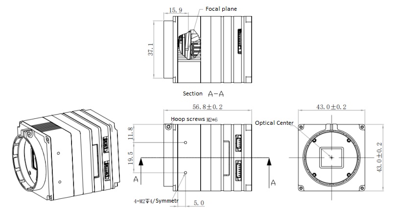
The core component of the system is the Focal Plane Array (FPA). The FPA is a grid of microscopic detector elements located precisely at the focal point of the lens. Each individual element on this grid corresponds to a single pixel in the final image. The density of this grid determines the camera's baseline spatial resolution.
Most uncooled FPAs utilize microbolometer technology. A microbolometer is a tiny Micro-Electromechanical System (MEMS). It consists of a thermally sensitive absorbing layer suspended above a readout integrated circuit (ROIC) by microscopic legs. These legs provide thermal isolation, preventing the heat from bleeding away into the substrate. The absorbing layer is typically made from Vanadium Oxide (VOx) or Amorphous Silicon (a-Si). Both materials possess high Temperature Coefficients of Resistance (TCR), meaning their electrical resistance changes dramatically with slight temperature shifts.
The physical conversion of energy happens at the microbolometer level. Incoming infrared energy passes through the lens and strikes the FPA. The suspended absorbing layer on each microbolometer captures this energy. As it absorbs the infrared radiation, the physical temperature of the microscopic pixel rises slightly.
Because the material has a high TCR, this tiny temperature increase causes a proportional change in its electrical resistance. The camera's electronics continuously pass a small bias current through every pixel on the grid. The ROIC measures the minute resistance change across every single pixel simultaneously. This process translates thermal energy into measurable electrical signals. The speed at which the pixel heats up and cools down is known as the thermal time constant, which dictates how well the camera can capture fast-moving objects without motion blur.
The ROIC outputs an analog voltage signal for each pixel. An Analog-to-Digital Converter (ADC) transforms these voltages into digital values. This raw digital data is inherently noisy. Microbolometers suffer from fixed pattern noise due to slight manufacturing variations between pixels. To correct this, the camera performs a Non-Uniformity Correction (NUC).
NUC is a mechanical shutter process. A small shutter drops in front of the sensor, presenting a uniform temperature field. The processor reads this flat field and calculates offset values for every pixel. This recalibrates the sensor, eliminating image noise and thermal drift. The result is a clean, normalized digital map of the scene. You will hear an audible click when the camera performs this action.
Embedded processors then map these digital values to a specific color palette. They assign different colors or grayscale tones to different intensity levels. For example, the Ironbow palette is popular for industrial inspections, while White Hot or Black Hot are standard for security. This mapping creates the visible thermogram. When using a calibrated Infrared Imaging Camera, the processor also applies radiometric algorithms. These algorithms assign specific, accurate temperature values to individual pixels. Users can then set Isotherms to trigger visual alarms when specific temperature thresholds are breached.
Comparing the two primary sensor architectures is vital for system design. You must evaluate these technologies based on performance requirements, maintenance lifecycles, and the operational environment.
Uncooled sensors operate at or near room temperature. They do not require active cryogenic cooling mechanisms. Instead, they rely on simple thermoelectric temperature stabilization to keep the sensor package at a consistent operating baseline. This design dominates the commercial and industrial markets.
The advantages of uncooled systems are significant. They feature lower mechanical complexity and easier deployment. Without a cryocooler, they have zero maintenance requirements regarding cooling mechanisms. They boast a much smaller form factor and draw less power. They are designed for continuous, uninterrupted operation over many years, making them ideal for fixed perimeter security and 24/7 condition monitoring.
However, uncooled sensors have distinct limitations. They possess lower thermal sensitivity compared to cooled variants. They also have slower response times. The physical heating and cooling of the microbolometer pixel takes a fraction of a millisecond. This thermal time constant makes them less suitable for capturing extremely fast-moving objects, such as aircraft or high-speed manufacturing webs, without introducing motion blur.
Cooled thermal detectors utilize integrated mechanical cryocoolers, typically Stirling cycle engines. These coolers lower the physical temperature of the sensor to cryogenic levels, usually around 77 Kelvin (-196°C). Common detector materials for these systems include Indium Antimonide (InSb) or Mercury Cadmium Telluride (MCT). They generally operate in the MWIR band.
This extreme cooling eliminates thermally induced dark current noise within the sensor itself. By removing this internal noise, the sensor achieves incredible sensitivity. It can detect minute temperature differences that uncooled sensors completely miss. The integration time is also extremely fast, operating in microseconds rather than milliseconds, allowing for the crisp capture of high-speed events.
Cooled sensors are absolute necessities for specific high-end applications. They are required for border security, aerospace tracking, and optical gas imaging (OGI). When you need to identify a vehicle from 15 kilometers away or visualize a fugitive methane leak at a refinery, the sensitivity and crisp imaging of a cooled MWIR sensor are unmatched.
Noise Equivalent Temperature Difference (NETD) defines a camera's thermal sensitivity. It is measured in millikelvins (mK). A lower NETD value means the camera can distinguish smaller temperature differences. Uncooled sensors typically feature an NETD between 30mK and 50mK. High-performance cooled sensors often achieve an NETD of less than 15mK, providing vastly superior image contrast in challenging environments.
The primary trade-off involves severe maintenance intervals. Mechanical cryocoolers rely on moving parts operating at extreme speeds and temperatures. These coolers require complete factory rebuilds every 10,000 to 15,000 hours of operation. This translates to significant operational downtime. If a cooled camera runs continuously, the cooler will fail and require replacement roughly every 14 to 18 months. You must factor this maintenance cycle into your deployment strategy, especially if the cameras are mounted on inaccessible towers or remote off-grid locations.
Clarifying the distinction between true thermal imaging and active illumination technologies is critical. Confusing these two distinct technologies leads to severe specification errors and field failures.
True thermal cameras are entirely passive devices. They emit absolutely no energy into the environment. They act solely as receivers, capturing the natural heat signature radiated by objects in their field of view. They do not require any ambient light to function.
This passive nature provides massive advantages for covert security operations. Because they emit no light, they cannot be detected by visual means. They operate flawlessly in zero-light environments, deep inside tunnels, or on overcast, moonless nights. Furthermore, a true thermal imaging camera is completely immune to visual camouflage. If a target is warmer or cooler than the background, it will be detected, regardless of its color or pattern. They also perform exceptionally well in heavy foliage, where body heat easily contrasts against cold vegetation.
Active IR technology operates on a completely different principle. It uses an infrared illuminator, typically an array of IR LEDs, to cast near-infrared light into the scene. A standard CMOS or CCD image sensor captures this reflected light. The camera simply has its IR-cut filter removed to allow the near-infrared wavelengths to hit the sensor.
Active IR has severe physical limitations. The detection range is entirely bottlenecked by the power of the illuminator. If the IR light cannot reach the target and bounce back, the camera sees nothing. Additionally, active IR cannot see through smoke, fog, or heavy rain. The particulate matter scatters the near-infrared light, blinding the camera with a white-out effect similar to turning on high-beam headlights in a snowstorm. Finally, active IR systems possess a complete lack of temperature measurement capabilities. They only measure reflected light, not emitted heat.
Key technical specifications directly impact image quality, measurement accuracy, and application suitability. You must evaluate these metrics carefully against your specific operational requirements.
Thermal resolution standards differ significantly from visible-light cameras. While a standard security camera might boast 4K resolution (3840x2160), thermal arrays are much smaller. Common thermal resolutions include 320x240, 640x480, and 1024x768. Manufacturing large, defect-free focal plane arrays from exotic materials is exceptionally difficult. Therefore, lower resolutions are standard in thermography.
Pixel pitch is a critical metric. It measures the physical distance between the centers of two adjacent pixels on the FPA, typically expressed in micrometers (µm). Older sensors used a 17µm pitch. Modern sensors frequently use a 12µm pitch. A smaller pixel pitch allows more pixels to fit onto a smaller sensor area. This increases the camera's ability to resolve distant details without requiring a massive, heavy lens.
We evaluate NETD to understand a camera's baseline performance. Measured in millikelvins (mK), lower numbers indicate a better ability to distinguish subtle temperature differences. An NETD of 30mK will produce a cleaner, higher-contrast image than a camera with an NETD of 50mK, especially in low-contrast environments like a foggy harbor or a cold, rainy perimeter.
Standard accuracy tolerances for radiometric cameras are typically ±2°C or ±2% of the reading, whichever is greater. However, field accuracy depends heavily on environmental variables. Incorrect emissivity settings, unknown atmospheric transmittance, or uncalibrated reflected apparent temperature will easily push the actual measurement error far beyond the ±2°C specification. Proper operator training is required to maintain accuracy.
The relationship between focal length and Field of View (FOV) dictates target detection ranges. A longer focal length creates a narrower FOV, magnifying distant targets. We use Johnson's Criteria to define these ranges mathematically based on the number of pixels covering the target's critical dimension.
Detection: Requires 1.5 pixels across the target. The operator can see something is there, but cannot classify it.
Recognition: Requires 6 pixels across the target. The operator can classify the object (e.g., a human versus a vehicle).
Identification: Requires 12 pixels across the target. The operator can determine specific details (e.g., a human carrying a rifle versus a shovel).
Narrow FOV lenses present a major trade-off. While they provide excellent long-range observation, they destroy situational awareness. A 100mm lens might have a FOV of just a few degrees. You can see a target miles away, but you are blind to anything happening just outside that narrow cone of vision.
To solve this, a Long Range Thermal Imaging Camera often requires Pan-Tilt-Zoom (PTZ) housings and continuous optical zoom lenses. Continuous zoom allows the operator to maintain a wide FOV for scanning the horizon. Once a target is detected, they can optically zoom in, narrowing the FOV to achieve the pixel density required for recognition and identification. The PTZ mechanism allows tracking of moving targets over vast distances.
Raw thermal video is only part of the solution. Onboard edge analytics transform the camera into an automated sensor. Modern thermal cameras feature embedded algorithms for line crossing, intrusion detection, and fire detection. Radiometric models include temperature alarms that trigger automatically if a transformer or bearing exceeds a safe operating threshold.
Integration protocols dictate how this data moves into your broader network. Standard security protocols like ONVIF allow the thermal video and analytic alarms to tie seamlessly into standard Video Management Systems (VMS). For industrial monitoring, protocols like Modbus or MQTT are required. These protocols allow the camera to push raw temperature data directly into SCADA networks or industrial control systems for automated process control.
A thermal imaging camera is a complex measurement instrument, not just a visual tool. Its effectiveness relies entirely on the precise conversion of IR radiation to electrical signals. To ensure successful deployment, take the following actions:
Calculate the required pixel-on-target metrics using Johnson's Criteria before selecting any lens or sensor resolution.
Audit your deployment environment for highly reflective surfaces and adjust emissivity settings within the camera's software accordingly.
Verify that your selected hardware supports the necessary integration protocols, such as ONVIF for security or MQTT for industrial SCADA networks.
Establish a strict maintenance schedule if deploying cooled systems, accounting for the required cryocooler rebuild intervals.
A: No. Thermal cameras detect the surface temperature of the first solid object in their line of sight. They cannot penetrate walls, metal enclosures, or even standard glass. If a heat source inside a building warms the exterior wall, the camera will detect the heated wall, not the internal source itself.
A: Thermal cameras generally have much lower resolutions than visible-light cameras. Additionally, if the environment lacks thermal contrast, the image will appear flat and lack crisp edges. Proper focus and periodic Non-Uniformity Correction (NUC) help improve clarity.
A: Yes. Heavy rain, dense fog, and snow scatter and absorb infrared radiation. This atmospheric attenuation reduces the camera's detection range and image contrast. While thermal cameras perform better than visible-light cameras in these conditions, their performance is still degraded by severe weather.
A: These are visual mapping preferences. In White Hot, warmer objects appear white or lighter gray, while cooler objects appear black. In Black Hot, the mapping is inverted; warmer objects appear black. Security personnel often toggle between them depending on the environment to maximize target contrast.
A: For security applications, factory calibration is usually sufficient for the life of the camera. For radiometric applications requiring precise temperature measurements, annual recalibration by the manufacturer or a certified lab is recommended to maintain the standard ±2°C accuracy tolerance.
A: The clicking sound is the mechanical shutter activating during the Non-Uniformity Correction (NUC) process. The shutter drops in front of the sensor for a fraction of a second to provide a uniform temperature field, allowing the camera to recalibrate and eliminate image noise.


