
English
Are long-range surveillance demands increasing in your projects? Integrating a camera block into custom housings can cause critical system failures if not executed flawlessly. Poor wiring or network setups frequently lead to severe latency, dropped frames, or erratic Pan-Tilt-Zoom behavior. In this comprehensive guide, we dive deep into the hardware and protocol configurations required to build robust security equipment. We will walk you through the precise steps to seamlessly merge these core optical components into your custom surveillance ecosystem.
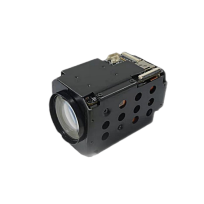
Think of a block camera as the central optical and processing engine for Pan-Tilt-Zoom domes, ruggedized border cameras, and specialized surveillance units. It physically houses the motorized lens assembly, the CMOS image sensor, and the Image Signal Processor on a single compact chassis. Grasping the architectural nuances between module types is your foundational step toward a successful hardware deployment.
An 100X 8MP Super Starlight Optical Zoom Module relies on the precise physical movement of internal glass elements to alter the focal length. Unlike digital magnification, which merely crops and enlarges pixels, true optical scaling preserves the native resolution of the sensor. This mechanical approach ensures that a target one kilometer away retains sharp edge details. Such clarity is an absolute necessity for facial recognition or license plate reading in critical infrastructure protection.
Alternatively, an 25X 8MP IP Zoom Camera Module integrates a network encoding board directly onto the camera block. This internal board compresses raw video data utilizing H.265 or H.264 codecs. It then outputs the stream via a standard Ethernet interface. System integrators heavily favor these networked units because they allow for direct IP connectivity. This drastically simplifies the internal architecture by eliminating the need for bulky external video encoders.
For ultimate flexibility, an OEM Zoom Block Module is engineered as a bare-bones, highly adaptable unit. Designed specifically for equipment manufacturers, these blocks output raw or uncompressed digital video like LVDS. They grant mechanical engineers the freedom to design custom exterior housings, specialized decoding boards, or unique form factors like drone gimbals and deep-sea submersibles.
To streamline your design phase, refer to this practical selection matrix. It compares core specifications to help you match the right hardware with your deployment environment.
Module Category | Output Interface | Key Engineering Advantage | Ideal Application Scenario | Example Specification |
|---|---|---|---|---|
Ultra-Long Range Optical | LVDS / Ethernet | Zero resolution loss at maximum magnification | Border patrol, coastal defense, military bases | 100X Optical, 8MP 4K, Super Starlight |
Networked IP Module | RJ45 Ethernet | Built-in encoding, direct VMS integration | City surveillance, traffic monitoring, commercial PTZ | 25X Optical, 8MP, H.265 Encoding |
Raw OEM Block | LVDS / MIPI | Ultra-low latency, maximum physical adaptability | UAV gimbals, robotic inspections, custom housings | Uncompressed 4K video, compact chassis |
Successful assembly requires meticulous preparation long before any physical connections are attempted. Failing to match power, data, and thermal specifications can result in permanent hardware damage. Worse yet, it can cause unstable operation during a critical security event.
Zoom mechanisms utilize precision stepper motors to drive heavy glass lens elements. Consequently, these motors demand a highly stable power supply, typically ranging from 9V to 12V DC. Engineers must account for sudden current spikes. A unit might only draw 300mA during standby. However, initiating a rapid pan-tilt maneuver alongside an autofocus sequence can push the draw well above 1.5A. Voltage drops caused by insufficient wire gauge will immediately force the Image Signal Processor to reboot. This often causes the autofocus algorithm to fail just as you are tracking a fast-moving subject.
Selecting the correct video output interface dictates the design topology of your entire control board. Specifically, LVDS delivers ultra-low latency uncompressed digital video under 10 milliseconds. This makes it ideal for direct board-to-board OEM integration. In contrast, standard Ethernet provides networked IP streams suited for direct Video Management System integration. EX-SDI or HD-SDI offers digital coaxial transmission for broadcast or specialized industrial monitoring. You must precisely match the module output interface to the overarching architecture of your surveillance network.
Modern high-performance 8MP sensors and processing chips generate a massive thermal footprint. If this heat is not aggressively dissipated, the sensor will introduce thermal noise. This appears as heavy grain into the image. Furthermore, the processor may throttle its performance to prevent melting. Integration designs must incorporate high-conductivity thermal pads connecting the main processor to the metal chassis. The external dome should also feature passive aluminum heat sinks or active internal airflow mechanisms. This maintains ambient temperatures within the rigorous negative 30 to positive 60 degrees Celsius operating standard.
Wiring an OEM block requires surgical precision. The micro-interfaces are exceptionally delicate. Improper seating causes immediate signal degradation or catastrophic short circuits.
Most raw modules utilize a 30-pin micro-coaxial cable for LVDS video output. When seating this fragile ribbon, technicians must ensure the microscopic pins are perfectly aligned. Applying uneven downward pressure can bend a pin by a fraction of a millimeter. This leads to missing color channels or a complete black screen. It is highly recommended to use electrostatic discharge safe tweezers during assembly. Secure the final connection with high-temperature Kapton tape to prevent the cable from dislodging during high-speed rotations.
To manipulate the zoom and focus motors, the unit must receive serial data commands. This communication is typically achieved via RS485, RS232, or TTL interfaces. When stripping and wiring RS485 cables, double-check that the positive and negative data lines are not inverted. Establishing a common ground between the main control board and the camera chassis is mandatory. Without a shared ground, electrical loops corrupt the serial data packets. This causes the camera to spin erratically or ignore joystick inputs entirely.
Upon applying clean DC power, a fully functional unit will immediately initiate a mechanical calibration sequence. You will observe the lens automatically extending to its maximum telephoto position and then retracting to its widest angle. This brief physical exercise allows the internal optical encoders to establish their absolute zero-point reference. If the lens stutters, emits a grinding noise, or fails to move, cut the power instantly. Such symptoms indicate a mechanical obstruction or a severe voltage drop across the power lines.
Once the hardware is securely mounted and wired, networked units must be digitally configured to communicate with the broader security infrastructure.
By default, most IP-enabled blocks ship with a static IP address or have DHCP enabled. Network engineers must access the built-in web server via a standard browser. You must assign a permanent static IP address that perfectly aligns with the specific subnet mask of the security network. During this initial handshake, administrators are strictly required to establish secure credentials. Disabling default factory passwords is the first line of defense in complying with modern cybersecurity frameworks.
For a camera to communicate seamlessly with third-party enterprise recorders, ONVIF compliance is not just optional. It is absolutely critical. Profile S ensures basic video streaming and control compatibility. Profile T supports advanced video encoding like H.265 and metadata streaming. Verify that the correct ONVIF profiles are toggled on. Ensure a dedicated ONVIF user account exists within the network settings.
To optimize network bandwidth, these units typically output multiple real-time streams simultaneously. The main stream is configured for maximum resolution like 8MP at 30 frames per second. This high bitrate stream routes directly to the recorder for forensic-level analysis. Concurrently, the sub-stream is dialed down to a lower resolution and bitrate. This lightweight stream is ideal for remote viewing over cellular networks or populating multi-camera grid displays in a bustling command center.
To achieve seamless operation in physical security environments, engineers must establish precise communication between the overarching control system and the internal motors. Without proper protocol configuration, operators experience frustrating latency, inaccurate positioning, or complete failure of movement functions.
Originally developed for broadcast, the VISCA protocol remains the undisputed industry standard for block cameras. It utilizes a hierarchical network structure, typically operating over RS232 or TTL serial interfaces. Engineering best practices dictate using VISCA for complex integrations. It offers granular low-level control over the Image Signal Processor.
A standard VISCA command packet consists of a header, message, and terminator. Sending a specific hexadecimal string instructs the module to execute a zoom or focus command at a variable motor speed. Developers must ensure the baud rate of the controller matches the default baud rate of the camera to prevent packet loss. Advanced VISCA commands also allow integrators to query the camera for its absolute zoom position. This is a critical feature for automated drone tracking systems.
While VISCA dominates internal lens control, Pelco-D and Pelco-P are legacy protocols frequently utilized in RS485 environments. Pelco-D uses a standard seven-byte frame consisting of a synchronization byte, address byte, command bytes, data bytes, and a checksum. When retrofitting a modern block into an older hybrid security infrastructure, configuring the decoding board to accept Pelco-D commands is vital. This ensures backward compatibility with existing physical joysticks and legacy control keyboards.
Modern surveillance architectures are rapidly shifting away from hardwired serial control. Networked units translate digital commands into physical motor movements through their internal encoding boards. By leveraging ONVIF Profile S specifications, a management system can send XML-based requests over the Ethernet network. The internal firmware parses these network commands and instantly converts them into the appropriate VISCA signals for the lens block. This soft-control eliminates the need for separate RS485 wiring. It significantly streamlines the hardware footprint inside the weatherproof housing.
Deploying security equipment in climate-controlled indoor environments requires minimal configuration. However, border control, maritime surveillance, and heavy industrial monitoring demand rigorous optimization. Integrators must carefully calibrate the processor to handle blinding glare, pitch-black nights, and dynamic atmospheric interference.
Standard surveillance sensors struggle to capture usable color data in environments with less than minimal illumination. To overcome this, engineers utilize Super Starlight technology. This combines massive-aperture lenses with highly sensitive back-illuminated CMOS sensors. This setup allows security systems to maintain full-color video feeds in near-total darkness without relying on covert infrared illumination.
To truly optimize low-light performance, integrators must manually tune the Auto Gain Control and Digital Noise Reduction settings. Increasing gain amplifies the electrical signal to artificially brighten the image. Unfortunately, it simultaneously introduces digital snow. Applying aggressive noise reduction smooths out this grain but can cause severe motion blur on moving vehicles. Empirical field testing is required to find the exact threshold that balances image brightness with crisp motion clarity.
Long-range surveillance introduces significant challenges for auto-focus algorithms. When a camera tracks a moving target across a complex cluttered background, the lens may begin hunting. It rapidly shifts focus back and forth as the algorithm struggles to identify the primary subject.
To prevent this dizzying effect, adjust the focus mode based on the deployment scenario. Normal continuous focus evaluates the scene constantly, making it suitable for static perimeter monitoring. However, for active tracking, zoom-trigger focus is vastly superior. In this mode, the camera only recalculates focus immediately after a zoom command is executed. This prevents the lens from hunting when a foreground object temporarily obscures the field of view.
Atmospheric haze, heavy fog, and thermal distortion severely degrade image quality at extreme focal lengths. High-performance units utilize two distinct methods to combat this. Digital defog algorithms analyze the video feed in real-time, artificially enhancing contrast and sharpness in low-visibility zones. Optical defog involves mechanically deploying a special filter over the sensor. This allows the camera to capture near-infrared light that penetrates dense fog far more effectively than the visible light spectrum.
Furthermore, True Wide Dynamic Range must be enabled when monitoring areas with extreme high-contrast lighting. A prime example is a dark tunnel entrance facing the glaring sun. This technology captures multiple exposures of the exact same frame at different shutter speeds and seamlessly merges them. It ensures that both heavily shadowed areas and brightly lit backgrounds remain perfectly visible and detailed.
Even with meticulous blueprinting, integrating specialized blocks into custom security housings can present frustrating technical hurdles. System integrators should adopt a systematic diagnostic approach. This rapidly isolates hardware, network, and optical anomalies.
When the unit receives power but fails to output a video signal, the fault typically lies in the physical interface. For LVDS setups, inspect the micro-coaxial pin seating under a magnifying glass. A misalignment of a fraction of a millimeter results in total signal loss. If utilizing an IP setup, connect the module directly to a diagnostic laptop via a network switch. Bypass the overarching network and use a packet sniffer to verify if the camera is actively broadcasting its stream.
A frequent issue reported during field testing is the inability of the camera to lock focus at extreme focal lengths. At high magnification, minor smudges or dust particles on the outer housing glass are drastically magnified. This confuses the contrast-detection algorithm. Ensure the housing glass is optically pristine. Additionally, access the processor settings and manually increase the minimum focus distance parameter. If the camera is zoomed to 100X, it physically cannot focus on a target only twenty meters away. Increasing this distance prevents the algorithm from attempting impossible calculations.
Delayed responses to operator joystick commands severely impact the efficacy of active security tracking. If sending VISCA or Pelco commands via RS485 yields no response, meticulously verify the baud rate, parity, and stop bit settings. A mismatch between the control board and the camera block results in unrecognized hex commands. For IP-based soft-control, command latency is almost always a symptom of network congestion. Ensure that the control packets are prioritized via Quality of Service protocols on your network switch.
Recent industry analyses and market trends indicate a massive shift in how security hardware is designed. The physical security sector is rapidly transitioning from passive video observation to active automated intelligence. Historically, camera blocks functioned strictly as optical data-gathering tools. They relied entirely on heavy backend servers or fatigued human operators to analyze the video feed.
Today, the integration of edge computing is fundamentally altering manufacturing standards. Driven by the need for faster response times and reduced server costs, modern modules are increasingly integrating dedicated Neural Processing Units directly onto the mainboard. This hardware evolution allows the camera to run complex deep learning algorithms locally at the edge of the network.
By processing data on the device itself, security systems drastically reduce the bandwidth required to transmit high-resolution video to centralized command centers. A modern PTZ camera can now autonomously lock onto a target, calculate the required zoom ratio, and track a subject across a perimeter without human intervention. In addition, these advanced units stream structured metadata alongside the standard video feed. This transforms raw optical data into instantaneous actionable security intelligence.
Meticulous hardware wiring and robust network setups are the bedrock of reliable surveillance infrastructure. Proper protocol matching ensures that your optical core communicates flawlessly with external controllers. This eliminates latency and tracking errors. Ultimately, the quality of your core components dictates the resilience of the entire security system.
Ready to upgrade your surveillance manufacturing line? Selecting an easily integrable, standardized module saves your engineering team countless hours during the research and development phase. It significantly reduces long-term maintenance costs in the field. Explore the high-performance Futurevision CCTV camera lineup to find the exact specifications your project demands. From ultra-long-range optical blocks to compact network modules, ensure your surveillance products are ready for the demanding environments of tomorrow.
Optical magnification utilizes precision mechanical lens movements to physically enlarge an image. This alters the focal length without any loss of sensor resolution. It ensures that a target captured at high magnification retains its full megapixel clarity. Conversely, digital zoom relies on software algorithms to artificially enlarge the existing pixels of an image. This inevitably results in heavy pixelation and a severe loss of evidentiary quality. In professional physical security applications, engineers almost exclusively rely on true optical lenses for critical identification.
Direct integration depends entirely on the output interface of the module. If you are utilizing an IP-enabled block that features a built-in network encoding board and supports ONVIF protocols, it can connect directly to a recorder via a standard Ethernet switch. However, if you are working with a raw OEM block that only outputs uncompressed digital signals like LVDS, it cannot interface directly. You must first route the signal through a compatible hardware encoding board to convert the raw video data into an IP-based stream.
Within the internal architecture of the camera itself, VISCA is the most widely adopted protocol for controlling the internal lens motors. It governs precise movement and parameter adjustments. However, when interfacing the completed camera assembly with external control keyboards or legacy infrastructure, Pelco-D and Pelco-P remain standard for RS485 serial communication. In modern networked environments, ONVIF profiles are the definitive standards for transmitting control commands over Ethernet.
Focus failure at extreme focal lengths is rarely a mechanical defect. It is typically an environmental or algorithmic issue. At maximum magnification, atmospheric interference such as heat waves, heavy humidity, or smog severely degrades image contrast. This confuses the contrast-detection auto-focus. To resolve this, ensure that the optical defog feature is enabled to cut through atmospheric moisture. Additionally, verify that the minimum focus distance parameter is set appropriately for long-range targets. If environmental interference is too severe, operators should switch the module to manual focus mode to securely lock onto static long-range subjects.
The choice depends entirely on your system architecture and engineering capabilities. LVDS provides ultra-low latency raw video. This is ideal if you are designing custom decoding boards, specialized drone gimbals, or highly integrated OEM systems. IP output features an onboard encoder. This allows direct connection to network switches and Video Management Systems. IP modules drastically reduce development time for standard security housings since the encoding hardware is already built-in.
Command latency usually stems from network congestion or mismatched communication settings. When soft-control packets compete with high-bitrate 4K video streams on the same unmanaged switch, severe delays occur. Implementing Quality of Service rules prioritizes control data over video data. Additionally, ensuring your decoding board matches the camera baud rate eliminates translation delays. Hardwired RS485 connections generally offer lower latency than network-based soft-control in highly congested network environments.


